Soft Actuator
design, algorithm, analysis
This is one of my project as an undergraduate within the BEAMS (Bio- Electro- And Mechanical Systems) at the Université libre of Bruxelles (Undergraduate) under Pr. Alain Delchambre. I was awarded a competitive summer research scholarship (out of 200 students in my program) during that time..
Background
Recent developments in soft robotics offers a safer and more flexible alternative to traditional steerable catheters in minimally invasive surgery and endoscopy. Soft robots navigate complex spaces with more dexterity and increases the safety of of surgical operations due to their robustness. In addition to their improved navigation capabilities, soft robots hold the promise of future autonomous actuators relieving professional practitioners of critical tasks. However, the intrinsic non-linear properties of the soft material and the infinite number of degrees of freedom have made it difficult to formulate a suitable mathematical model for a reliable control strategy.
Development
In this work, I explored the promise of data-driven techniques to bypass many of the difficulties encountered in modelling soft robots, specifically a one-degree-of-freedom pneumatic soft actuator prototype. However, this can be done only with a suitable set-up for extensive data collection.
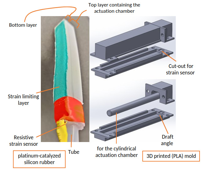
I prototyped 3D-printed molds to fabricate the actuator out of a common platinum-catalyzed silicones material into two distinct layers dictated by the moulding process: a semi-cylindrical top layer containing a cylindrical actuation chamber of 9 mm diameter and a rectangular plate-shaped bottom layer. I added a strain limiting layer below the latter to constrain the bending motion in one direction. I placed a 4.5” Flex sensor on top of the lower layer, as indicated by the small cut-out extruded onto the mould during the curing process. This position far from the neutral axis of the actuator guaranteed a large range of sensor readings. Silicone binded the layers together.
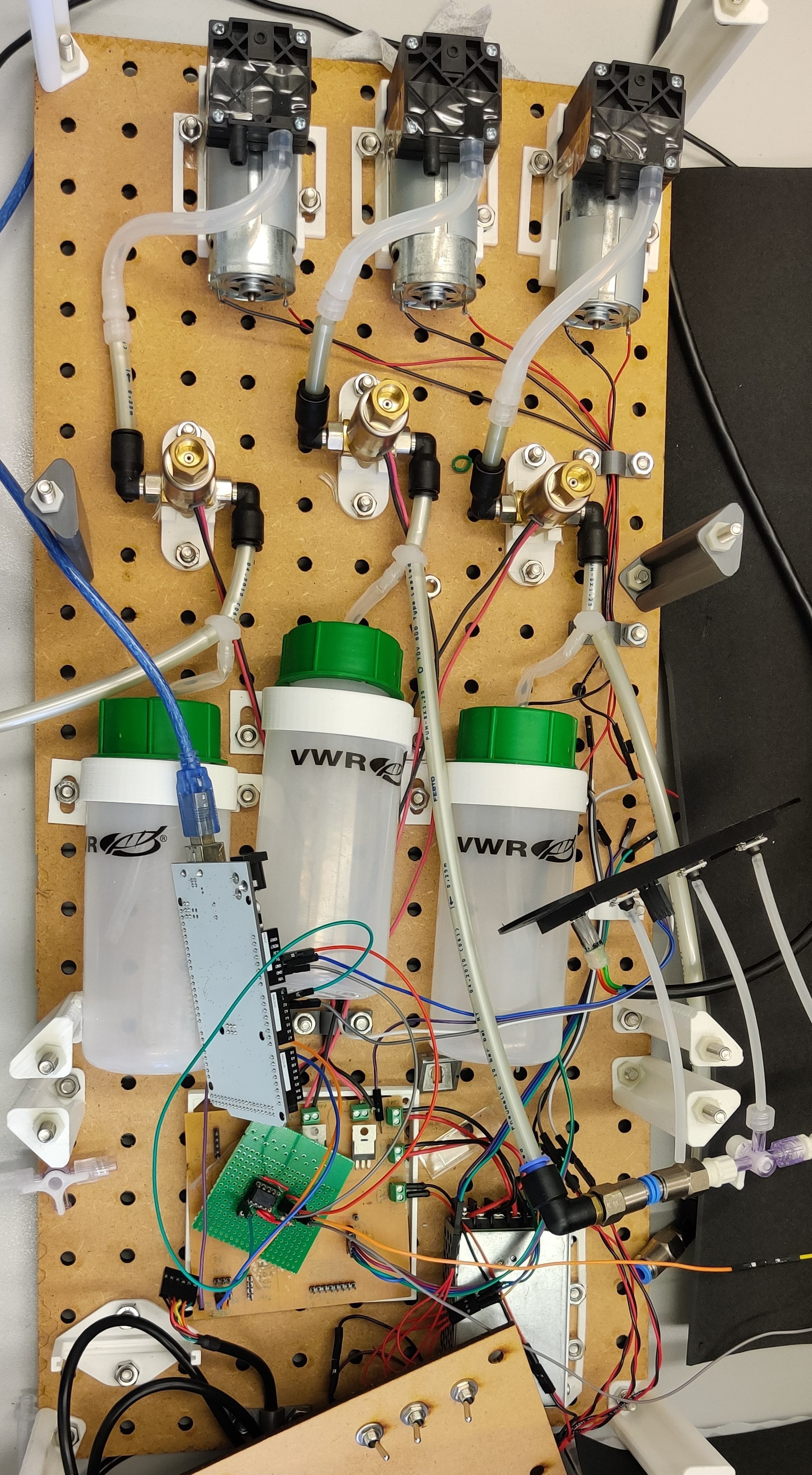
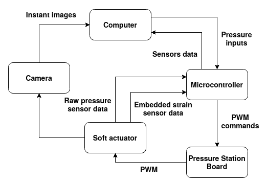
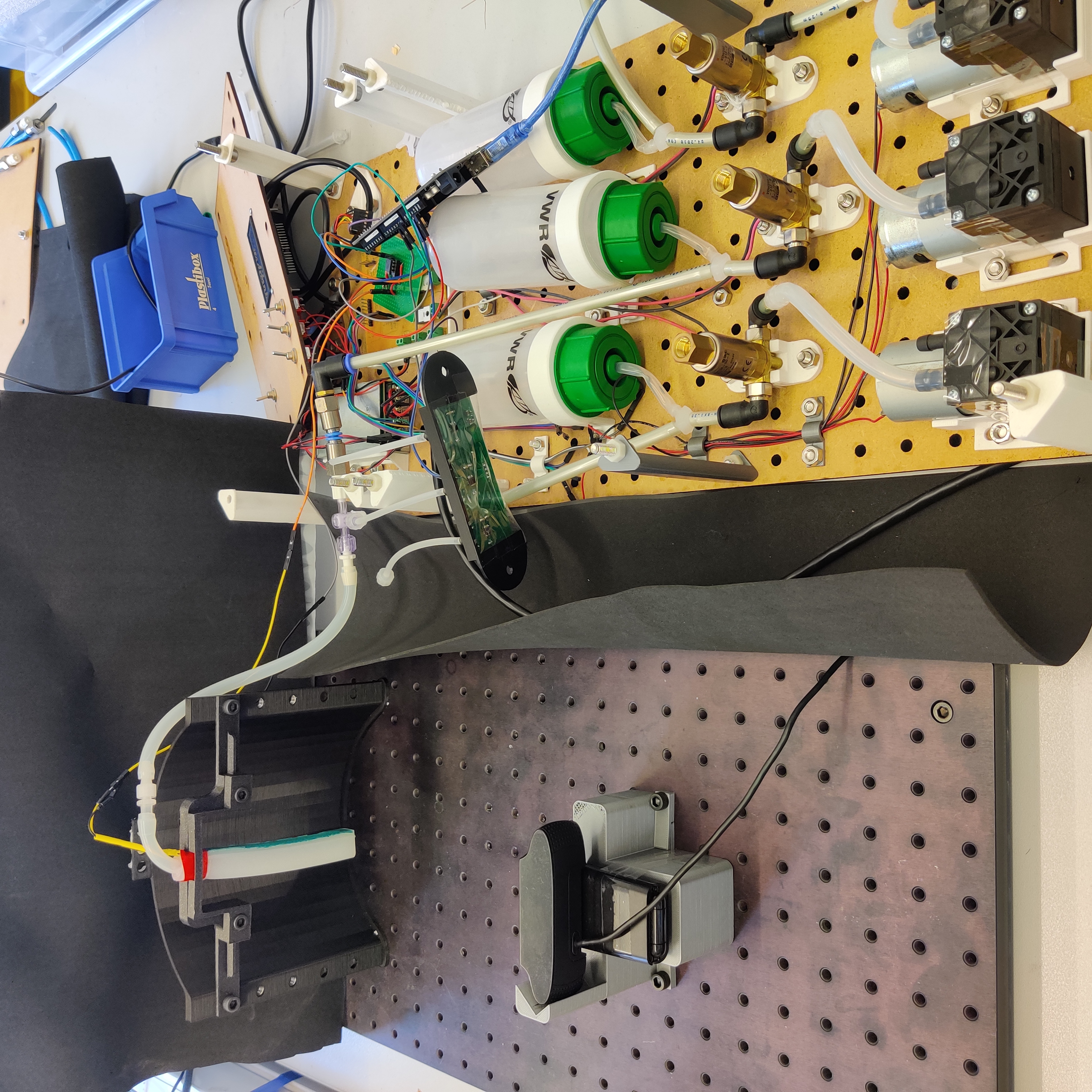
The objective was to gather 3 signal to represent the state of the actuator: the pressure in the chamber, the strain measured in terms of voltage, and an estimated radius of curvature extracted using image processing. I leveraged and customized an existing pressure station a PhD student initially built. Air was injected into the chambers using a 12V diaphragm pump and 3/2-way valves. I calibrated and used an analog differential pressure transducer coupled with an instrumentation amplifier, measuring pressure at the inlet of the actuator chambers (pressure uniformity was assumed with respect to the actuator). The air flow was controlled via the PWM duty cycle of the valves.
The set-up was a bit atypical as the chip controlling the pressure could only actuate the valves, so I implemented all filtering and control algorithms on another microcontroller which communicated over serial to both the pressure station and my laptop. I tuned a low-pass filter and a PI controller to track the reference pressure. All image processing was done on my laptop.

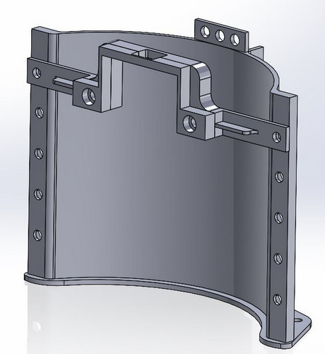
I decided to track directly the radius of curvature itself instead of a reference point as I believed it would help take into account the longitudinal expansion resulting from the bending which directly affects the radius of curvature. I considered a constant curvature of the actuator, e.g. the radius is “constant in space but variable in time” [1]. The actuator was mounted with the tip facing backwards against gravity on an 3D printer holder mounted on a base plate. Similarly, I mounted a calibrated camera and used a black background to facilitate image processing.
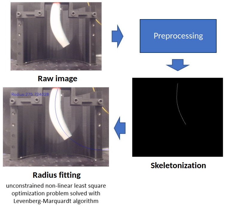
We didn’t have a motion capture system, so I coded up a bending curvature estimation algorithm in C++ alonside the overall data collection system. Given the fast transient dynamics of the actuator when bending, I needed a sufficiently high frame-rate (10 Hz) to capture those effects. The wjole image processing pipeline revolved around a “skeleteonizization” using Zhang-Suen thinning algorithm [2] after pre-processing the images. I manage to achieve a steady 20 FPS stream. I then retrieve the \(m\) 2D non-zero points \((x_i,y_i)\) for \(i=1,…,m\) from the resulting binary frame. Under the constant curvature assumption, this skeleton is the arc of a circle of radius \(R\) with center \(c=(c_x, c_y)\): \(R = \sqrt{(x - c_x)^2 + (y - c_y)^2}\)
We can then formulate the fitting of the circle as an unconstrained non-linear least square optimization problem:
I solved the optimization using Levenberg-Marquardt algortihm in C++. The initial guesses used were the mean of the initial binary coordinates. While this method was working ‘most of the time’, it still remains a local method and is sensitive to outliers.
Quick results
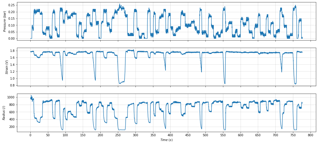
The strain signal is the most reliable to detect a bending motion and indicated the existence of a pressure threshold for the bending motion of the actuator.
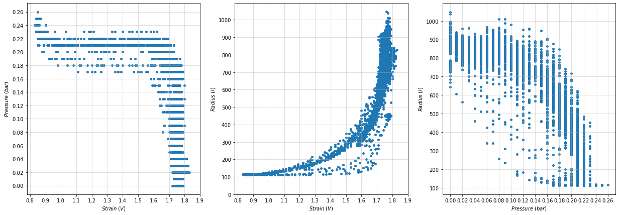
The direct comparison highlight hysteresis effects of the apparatus and confirmed the “exponential” nature of the relationship between the measured strain and the bending curvature (which I could observe qualitatively). For a laptop view, check LINK
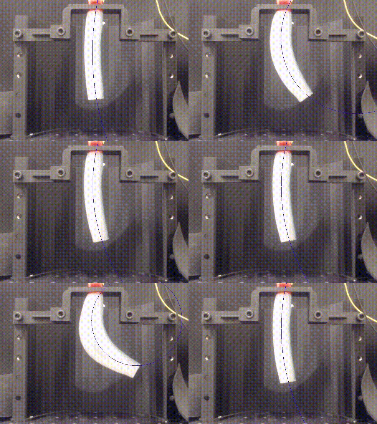
Some notes for improvement:
- I think the system would have performed better accuracy with a proper motion capture system such as OptiTrack instead of handcrafting a recognition algorithm. On the other hand, such system is expensive and deriving useful experiments from a camera allows quick iteration
- The pressure sensor resolution was limited to 0.1 bar, which was fairly high when considering to the perceived change of pressure.
- The Levenberg–Marquardt algorithm is an iterative algorithm converging only towards local minimum, which may or may not be a global minimum. The initialization could have been better.